

"Shell and tube heat exchangers are widely used in chemical processing, oil and gas, power generation, and other industrial applications. However, incorrect TEMA selection, tube-to-tubesheet leaks, and poor fabrication quality can lead to reduced efficiency, costly maintenance, and unplanned shutdowns."
Learn more about shell-and-tube heat exchanger designs and their industrial applications.
For plant engineers and procurement teams, choosing the right manufacturer involves more than comparing prices. It requires evaluating design suitability, material quality, inspection procedures, and long-term maintenance needs.
This guide explains how to select the right exchanger, prevent joint leakage, verify fabrication quality, and make informed purchasing decisions.
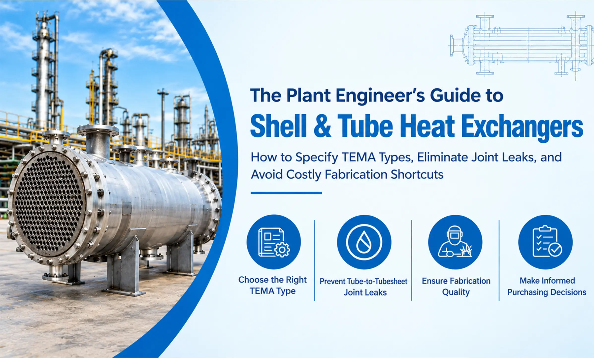
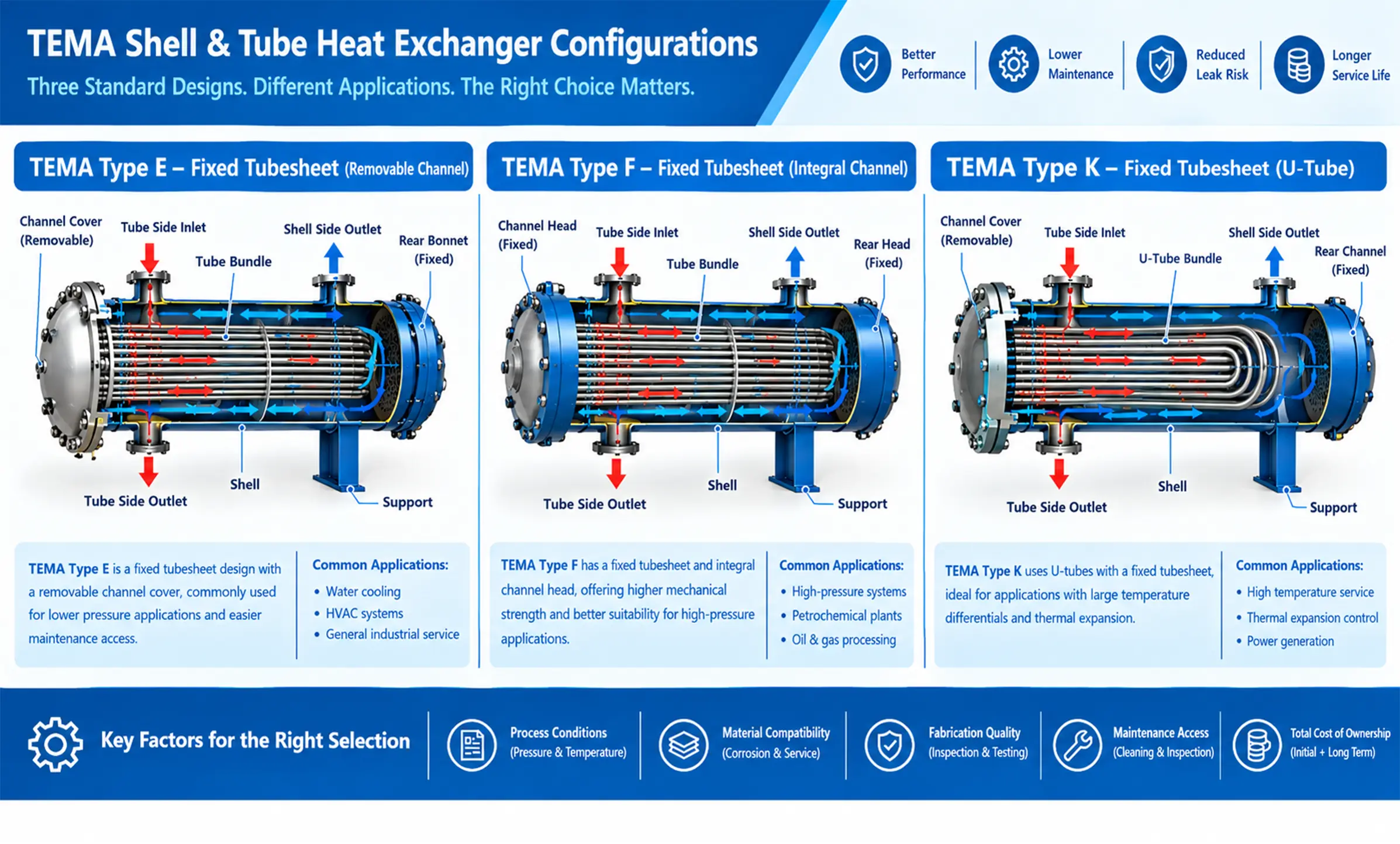
TEMA (Tubular Exchanger Manufacturers Association) provides standards for shell-and-tube heat exchanger construction and design. Selecting the correct configuration requires consideration of thermal expansion, fouling, cleaning access, operating conditions, and maintenance costs.
| Factor | Fixed-tubesheet | U-tube | Floating-head |
|---|---|---|---|
| Construction | Tubesheets fixed to shell | Tubes bent into U shape | One tubesheet can move relative to shell |
| Thermal expansion | Requires careful evaluation | Accommodates expansion through tube flexibility | Accommodates differential expansion |
| Tube-side cleaning | Generally accessible from tube ends | U-bends can be difficult to clean | Generally accessible with bundle removal |
| Shell-side cleaning | Often difficult mechanically | Easier when the bundle is removable | Generally easier with bundle removal |
| Maintenance | Relatively simple | Moderate complexity | More complex |
| Relative cost | Often lower | Often moderate | Often higher |
Actual cost and suitability depend on materials, pressure, temperature, and construction details.
Fouling-prone applications may benefit from removable bundles and accessible tube surfaces. U-tube designs offer thermal flexibility, but their bends can complicate mechanical cleaning. Before selecting a configuration, consider deposit location, cleaning methods, maintenance space, and bundle-removal requirements.
Different operating temperatures can cause the shell and tubes to expand at different rates. If the design cannot accommodate this movement, excessive stresses may damage tubes, joints, or the shell. Evaluate startup, shutdown, and temperature cycling when selecting a fixed-tubesheet, U-tube, floating-head, or expansion-joint arrangement.
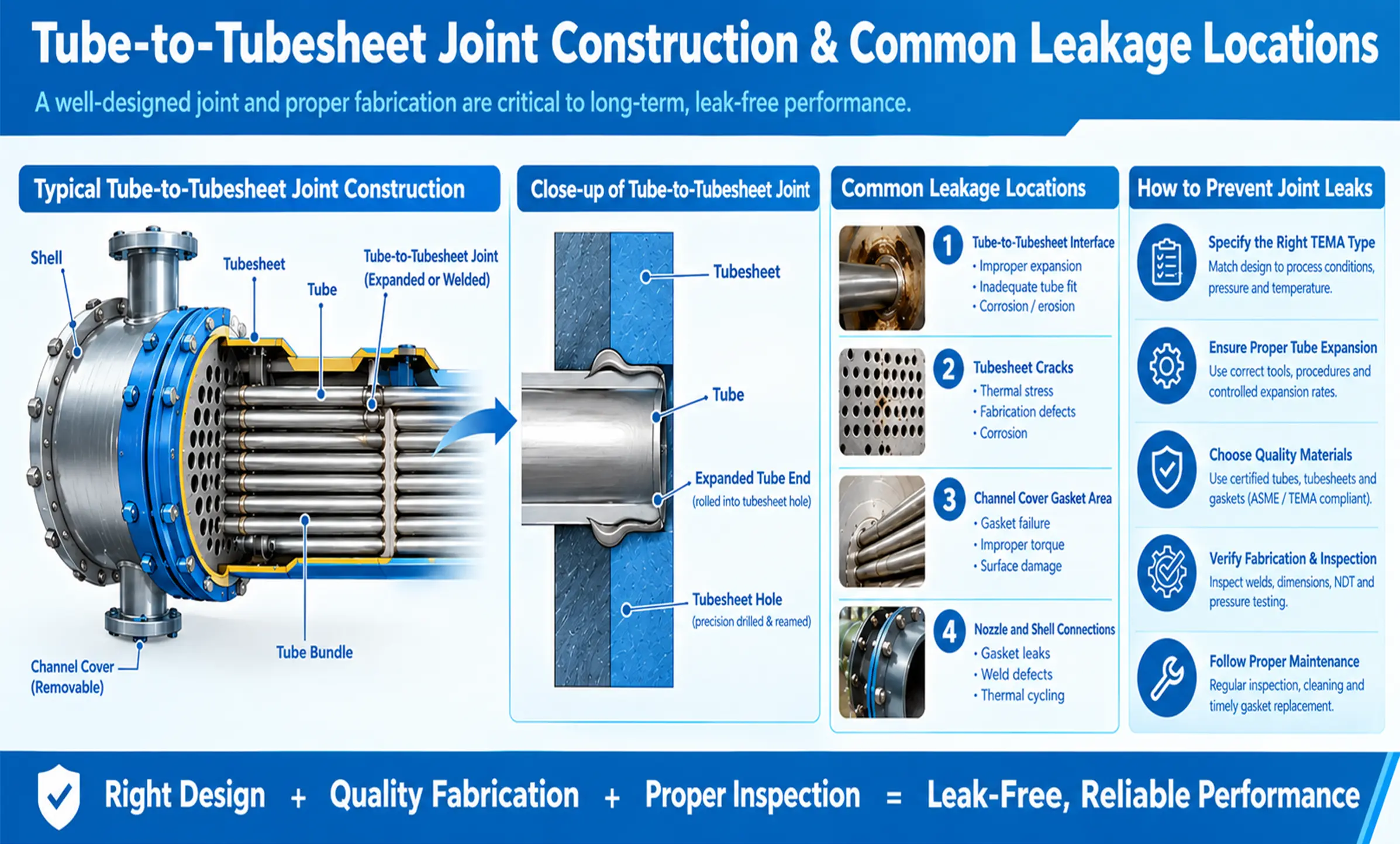
Tube-to-tubesheet joints separate the shell-side and tube-side fluids. Joint failure can cause cross-contamination, process interruptions, and safety risks. Common causes include incorrect tube expansion, defective welds, corrosion, vibration, and thermal cycling.
Leaks may result from poor tube-hole preparation, excessive or insufficient expansion, welding defects, corrosion, or mechanical fatigue. Investigate the leak location, operating history, and material condition instead of repeatedly repairing the visible defect.
| Joint type | Function | Main consideration |
|---|---|---|
| Mechanically expanded | Creates contact between the tube and tubesheet hole | Requires controlled expansion |
| Seal-welded | Provides a sealing weld | Must meet service and leakage requirements |
| Strength-welded | Weld carries specified structural loads | Requires appropriate design and inspection |
The correct method depends on operating conditions, materials, leakage consequences, and applicable construction requirements. Specify the joint design and acceptance criteria before fabrication.
Use approved pressure or leak tests, suitable visual examinations, and other appropriate inspection methods. Establish testing requirements before manufacturing and investigate recurring leaks to identify whether the cause is fabrication, corrosion, or operating conditions.
Poor fabrication can compromise equipment reliability even when the original design is correct. Buyers should verify material compliance, manufacturing tolerances, welding procedures, and inspection records.
Incorrect hole dimensions, rough surfaces, contamination, or uncontrolled tube expansion can weaken joint integrity. Confirm that the manufacturer follows approved procedures and documents the required dimensional and process checks.
Cracks, lack of fusion, and other unacceptable weld discontinuities may compromise equipment integrity. Unapproved material substitutions can also reduce corrosion resistance or alter mechanical properties. Verify material traceability, welding qualifications, and required heat treatment.
Review approved drawings, datasheets, material specifications, dimensional tolerances, and inspection plans. Establish inspection hold points for critical fabrication stages and verify that deviations are documented and formally accepted.
Pre-delivery inspection helps identify defects before installation makes access difficult and repairs more expensive. Testing and inspection requirements should follow the applicable construction code and purchase specification.
Hydrostatic testing is commonly used to assess pressure-boundary integrity. Shell-side and tube-side testing requirements depend on the design and approved procedure. Confirm test pressures, isolation arrangements, acceptance criteria, and documentation before testing begins.
| Method | Purpose |
|---|---|
| Visual testing (VT) | Examines visible surfaces and weld profiles |
| Liquid penetrant testing (PT) | Detects suitable surface-breaking defects |
| Magnetic particle testing (MT) | Detects certain surface and near-surface defects in ferromagnetic materials |
| Radiographic testing (RT) | Examines suitable internal discontinuities |
| Ultrasonic testing (UT) | Evaluates internal discontinuities or material thickness, depending on the procedure |
Not every method is necessary for every exchanger. The appropriate inspection scope depends on the material, weld type, construction code, and project requirements.
Request the applicable material certificates, traceability records, welding documentation, NDE reports, dimensional inspection records, pressure-test results, approved drawings, and final inspection release. Check that the documents correspond to the actual equipment and approved specifications.
Actual performance may differ from design expectations because of fouling, flow changes, instrumentation errors, or changes in process conditions. Compare operating data with the original design basis before considering repairs or replacement.
Deposits such as scale, corrosion products, and suspended solids can increase thermal resistance and restrict flow. Review inlet and outlet temperatures, flow rates, pressure drops, and cleaning history. Filtration, suitable fluid treatment, and planned cleaning may help prevent recurring fouling.
Baffles guide shell-side flow and support the tubes. Unsuitable spacing or geometry can contribute to excessive pressure drop, poor flow distribution, or vibration. Evaluate these factors during design and investigate actual operating conditions before identifying the root cause.
| Problem | Possible causes | Recommended checks |
|---|---|---|
| Reduced heat transfer | Fouling or low flow | Compare temperatures and heat duty |
| Increasing pressure drop | Deposits or restricted flow | Review pressure-drop trends |
| Joint leakage | Corrosion or joint defects | Locate and inspect the leak |
| Repeated tube failures | Erosion, vibration, or fatigue | Examine failure locations and operating history |
| Frequent cleaning | High fouling tendency | Review fluid quality and cleaning records |
These symptoms are indicators, not definitive diagnoses. Confirm the cause through operating data and appropriate inspection.
Incomplete specifications and unclear quotation exclusions can lead to delays, additional expenses, and equipment that does not meet operating needs. Align engineering, procurement, and quality requirements before placing the order.
Provide fluid properties, flow rates, inlet and outlet temperatures, heat duty, operating and design pressures, allowable pressure drops, fouling requirements, material specifications, applicable codes, inspection requirements, and delivery expectations. Identify any assumptions or missing information clearly.
| Evaluation factor | What to verify |
|---|---|
| Design | Suitability for operating conditions |
| Materials | Compliance and traceability |
| Performance | Heat duty and pressure-drop requirements |
| Quality | Inspection and testing scope |
| Delivery | Lead time and production schedule |
| Warranty | Coverage, exclusions, and remedies |
| Support | Spare parts and maintenance assistance |
Compare quotations on an equivalent scope and consider lifecycle expenses such as energy use, cleaning, maintenance labour, and downtime.
Confirm applicable standards, inspection records, delivery commitments, warranty conditions, spare-part availability, and technical support. Ask suppliers to identify deviations from your specification in writing before approving the order.
Reliability depends on suitable design, controlled fabrication, correct installation, and consistent maintenance. Including these requirements during procurement helps reduce avoidable failures.
Evaluate tube access, removable covers, bundle extraction, lifting arrangements, maintenance clearances, and cleaning compatibility. Ensure the plant has sufficient space and equipment to carry out maintenance safely.
Record leakage locations, deposit types, operating conditions, and maintenance history. Investigate whether the cause is fabrication, corrosion, vibration, thermal cycling, or fluid contamination. Correct the underlying cause rather than repeatedly repairing the symptoms.
Before approving a shell and tube heat exchanger, use this final inspection checklist to confirm that the equipment meets the required quality and safety standards.
Reliable shell and tube heat exchangers require appropriate TEMA selection, suitable materials, sound tube-to-tubesheet joints, controlled fabrication, and documented inspection.
Plant engineers can reduce maintenance costs and unplanned shutdowns by specifying operating conditions clearly, investigating recurring leaks, verifying manufacturing quality, and comparing suppliers on technical compliance rather than price alone.
The objective is to procure an exchanger that delivers reliable performance, supports safe maintenance, and meets the plant's long-term operating requirements.
Need a custom process cooling system or a high-pressure shell and tube heat exchanger engineered for a harsh chemical environment? Connect directly with our strategy and design team to optimize your project lifecycle from initial concept development straight through to final field execution.
Director – Business Development & Strategy, HEFT Engineers Pvt. Ltd
Contact Number: +91 9769063942
Follow HEFT: HEFT Engineers on Instagram →